
How to Commission an Agricultural Irrigation Pump Station
A practical commissioning sequence for verifying irrigation pump performance, controls, safety and operating interfaces before accepting the station—and checking it again under seasonal conditions.
Who should lead commissioning?
An appointed, competent lead coordinating qualified electrical, mechanical, controls and irrigation personnel, with clearly assigned acceptance authority. No. Verify simultaneous flow and total dynamic head, plus electrical input when assessing overall efficiency.
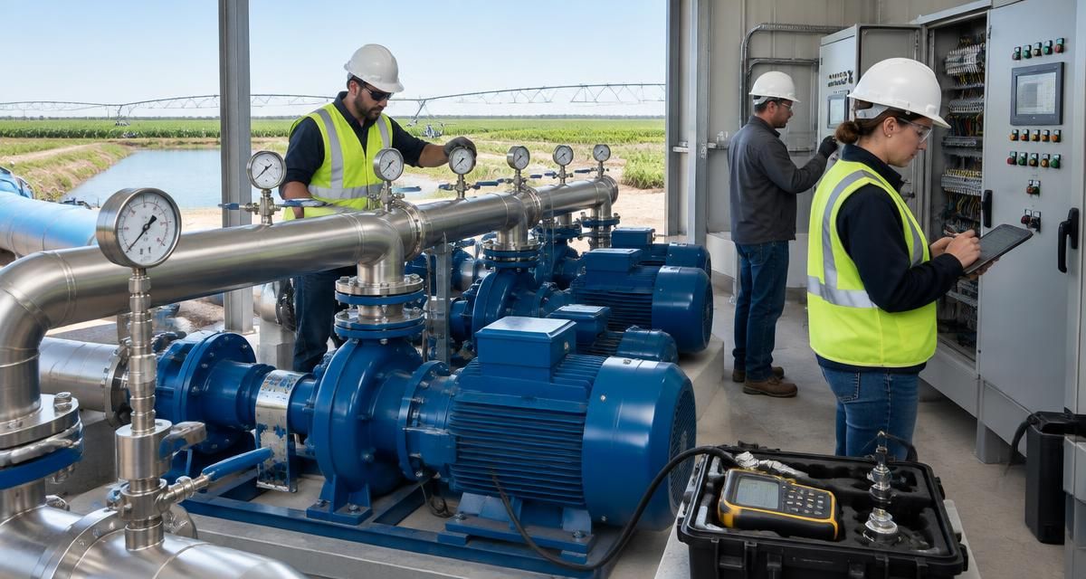
Key takeaways
- 1. Commission against approved duties, not simply running equipment: Commission an agricultural irrigation pump station by confirming mechanical and electrical readiness, then testing each approved operating duty with calibrated instruments.
- 2. Assemble the approved test basis: Before testing, collect the approved duty-point schedule, pump curves, motor and VFD data, hydraulic calculations, electrical drawings, control narrative, equipment instructions and contractual acceptance requirements.
- 3. Clear mechanical completion and safety gates: Inspect foundations, anchor bolts, alignment, guards, lubrication, pipe supports, valve orientation, strainers, suction arrangements, air-release provisions, drainage and instrument connections.
- 4. Install instruments that can support acceptance: Use instruments with current, traceable calibration records and ranges appropriate to the expected readings.
- 5. Start carefully and verify hydraulic performance: Follow the approved startup procedure for priming, venting and valve positioning; the correct sequence depends on pump type and system design.
1. Commission against approved duties, not simply running equipment
Commission an agricultural irrigation pump station by confirming mechanical and electrical readiness, then testing each approved operating duty with calibrated instruments. Verify flow, total dynamic head, electrical input, efficiency, controls, protective functions and recovery sequences. Compare recorded results with agreed acceptance criteria, correct deficiencies, train operators and hand over complete records. A pump that starts and produces pressure is not necessarily ready for acceptance. Use documented decision gates: permission to energize, permission to run, permission to test automatically, and permission to hand over. Assign an authorized person to approve each gate.
2. Assemble the approved test basis
Before testing, collect the approved duty-point schedule, pump curves, motor and VFD data, hydraulic calculations, electrical drawings, control narrative, equipment instructions and contractual acceptance requirements. Define duty points for relevant irrigation zones, source-water levels, filtration conditions and simultaneous demands—not just maximum flow. Record operating limits, test methods, tolerances, measurement boundaries and who witnesses acceptance. Use the pump sizing calculator and irrigation pump calculator to organize preliminary assumptions, not to replace the approved engineering basis. Resolve contradictions between drawings, equipment selections and operating requirements before proceeding.
3. Clear mechanical completion and safety gates
Inspect foundations, anchor bolts, alignment, guards, lubrication, pipe supports, valve orientation, strainers, suction arrangements, air-release provisions, drainage and instrument connections. Confirm required flushing, pressure testing and electrical inspections are documented. Check priming requirements and adequate submergence or suction conditions against the approved design. Qualified personnel should verify earthing, protection settings, phase sequence and safe rotation using the manufacturer's procedure; do not dry-run equipment to discover rotation. Establish isolation and lockout procedures, emergency access, communications and a safe discharge route. Keep personnel clear of rotating equipment and pressurized connections. Stop commissioning for unsafe electrical work, missing guards, uncontrolled leakage or unresolved suction deficiencies.
4. Install instruments that can support acceptance
Use instruments with current, traceable calibration records and ranges appropriate to the expected readings. Establish a test arrangement that measures suction and discharge conditions, flow, speed and true electrical input power. Confirm pressure-tap elevations, gauge reference, flowmeter installation requirements and whether nearby bends or valves affect readings. Measure power with suitable equipment at the agreed boundary, such as the VFD supply, rather than treating motor nameplate power or current alone as actual consumption. Qualified electrical personnel must perform electrical measurements. Log instrument identification, calibration status, water level and relevant operating conditions so later comparisons remain meaningful.
5. Start carefully and verify hydraulic performance
Follow the approved startup procedure for priming, venting and valve positioning; the correct sequence depends on pump type and system design. Begin in a controlled mode, watch for leaks, vibration, unusual noise, overheating and unstable suction, and stop if safe limits are approached. Once conditions stabilize, record simultaneous flow, pressures, speed and electrical power. Calculate pump total dynamic head from discharge-minus-suction total head, including pressure, elevation and velocity-head differences where relevant; discharge pressure alone is insufficient. Compare performance with the approved curve at actual speed. Hydraulic power is density × gravity × flow × head in consistent units. Dividing it by measured electrical input gives wire-to-water efficiency, not pump-only efficiency.
6. Compare evidence using agreed acceptance rules
Agree tolerances and measurement uncertainty before testing; there is no universal percentage that makes every station acceptable. Compare like-for-like boundaries and conditions, distinguishing pump efficiency from overall efficiency that includes motor and drive losses. If a result fails, check the measurements and operating configuration before changing equipment or control settings. Record any retest under the same defined method. The following comparison framework identifies evidence needed for acceptance without inventing project-specific limits.
| Check | Compare against | Acceptance evidence |
|---|---|---|
| Flow and head | Approved duty schedule and pump curve at test speed | Stable, simultaneous readings within agreed tolerances |
| Electrical input and efficiency | Approved performance basis and measurement boundary | Recorded power and reproducible efficiency calculation |
| Suction and mechanical condition | Design limits and manufacturer requirements | Acceptable suction conditions, leakage, vibration and temperature |
| Automatic operation | Approved control narrative and operating envelope | Successful sequencing without unstable cycling |
| Alarms and recovery | Cause-and-effect schedule | Witnessed protective actions, notifications and permitted restart |
7. Test operating combinations and VFD controls
Test each required pump individually and the approved parallel combinations, including duty/standby changeover where provided. Cover minimum demand, normal irrigation demands and peak demand without intentionally exceeding approved operating limits. Verify staging and destaging, speed limits, acceleration and deceleration settings, pressure control and interaction with zone valves. Check that parallel pumps share load acceptably and do not drive one another into unsuitable operating conditions. Low-demand operation deserves attention: hunting, frequent starts or operation below minimum permissible flow can undermine reliability. Confirm local, remote and manual modes retain the required protections, and save the final approved settings.
8. Prove alarms, filtration interfaces and recovery
Use an approved test script to demonstrate alarms and protective actions. Prefer controlled signal simulation where creating the actual condition would risk injury or equipment damage; document what was simulated and what was physically tested. Check both local indications and remote notifications, including acknowledgement and reset behavior. Coordinate filtration tests with the irrigation network because backwashing changes hydraulic demand and available downstream pressure. Plan power-interruption testing with qualified personnel and affected operators. The required outcome is safe, authorized recovery—not automatic restart in every installation.
- Verify specified low-suction or dry-run protection, abnormal pressure, motor/VFD faults and sensor-failure responses.
- Trigger filtration backwash; verify differential-pressure logic, sequencing, pump response and downstream pressure.
- Test specified valve-position and communications interlocks without bypassing essential protection.
- Demonstrate power-loss behavior, retained settings, restart permissives and staged recovery; prevent unexpected energization.
- Record each stimulus, expected response, actual response, witness and corrective action.
9. Close defects before acceptance
Maintain a punch list identifying each defect, its consequence, responsible party, closure evidence and required retest. Separate safety-critical and performance-blocking defects from minor documentation or finish items. Acceptance should not hide unresolved failures behind a general statement that the station operates. Where the contract permits conditional acceptance, state the outstanding obligations and operating restrictions explicitly. Common mistakes include testing only one zone, overlooking suction-level variation, assuming factory curves prove installed performance, adjusting controls without recording changes, and accepting alarms without checking their actions. Repeat affected tests after repairs; a successful initial run does not validate later modifications.
10. Train operators, hand over records and verify seasonally
Train operators through supervised starts, normal shutdowns, alarm response, isolation, filter operation and safe recovery. Confirm understanding through demonstration rather than attendance alone. Hand over signed test sheets, calibration records, as-built drawings, approved settings and backups, equipment manuals, maintenance requirements, warranties and the closed or explicitly accepted punch list. Name the authority accepting the station and record any limitations. Establish seasonal verification at representative source levels and irrigation demands, using comparable measurement points and operating conditions. Investigate changes in flow, head, power or cycling before attributing them to pump wear. Repeat relevant commissioning checks after significant equipment or control changes.
11. Make the next procurement step testable
If commissioning responsibilities remain unclear, update the irrigation RFQ or use the RFQ builder to specify duties, witness points, instrumentation, records, training and acceptance ownership. SeedMatchGroup is a human-led commercial agriculture platform supported by proprietary technology for projects from USD 250,000. Supplier outreach happens manually after human review. It is not a manufacturer, EPC, lender, certification body, open marketplace or direct connector, and does not guarantee supplier quotations, timing or outcomes.
Sources and further reading
For general irrigation engineering and management context, consult USDA NRCS National Engineering Handbook, Part 652: Irrigation Guide and ASABE Irrigation Systems Management. These references do not replace project-specific requirements or endorse SeedMatchGroup.
Turn "How to Commission an Agricultural Irrigation Pump Station" into your RFQ
Answer a few questions and we will draft a structured RFQ you can review, edit and submit to our independent supplier network.
Frequently asked questions
- Who should lead commissioning?
- An appointed, competent lead coordinating qualified electrical, mechanical, controls and irrigation personnel, with clearly assigned acceptance authority.
- Can pressure alone prove pump performance?
- No. Verify simultaneous flow and total dynamic head, plus electrical input when assessing overall efficiency.
- Must every possible pump combination be tested?
- Test approved operating combinations and verify that prohibited combinations are prevented by the specified controls.
- What if seasonal conditions are unavailable?
- Document unverified conditions and agree deferred testing, responsibilities and acceptance implications rather than declaring full verification.
- When should commissioning stop?
- Stop for unsafe conditions, operation outside approved limits or unreliable measurements that prevent defensible acceptance.
Move from reading to sourcing
The pages below carry the commercial detail for this topic — cost ranges, supplier verification, specification checklists and financing routes.